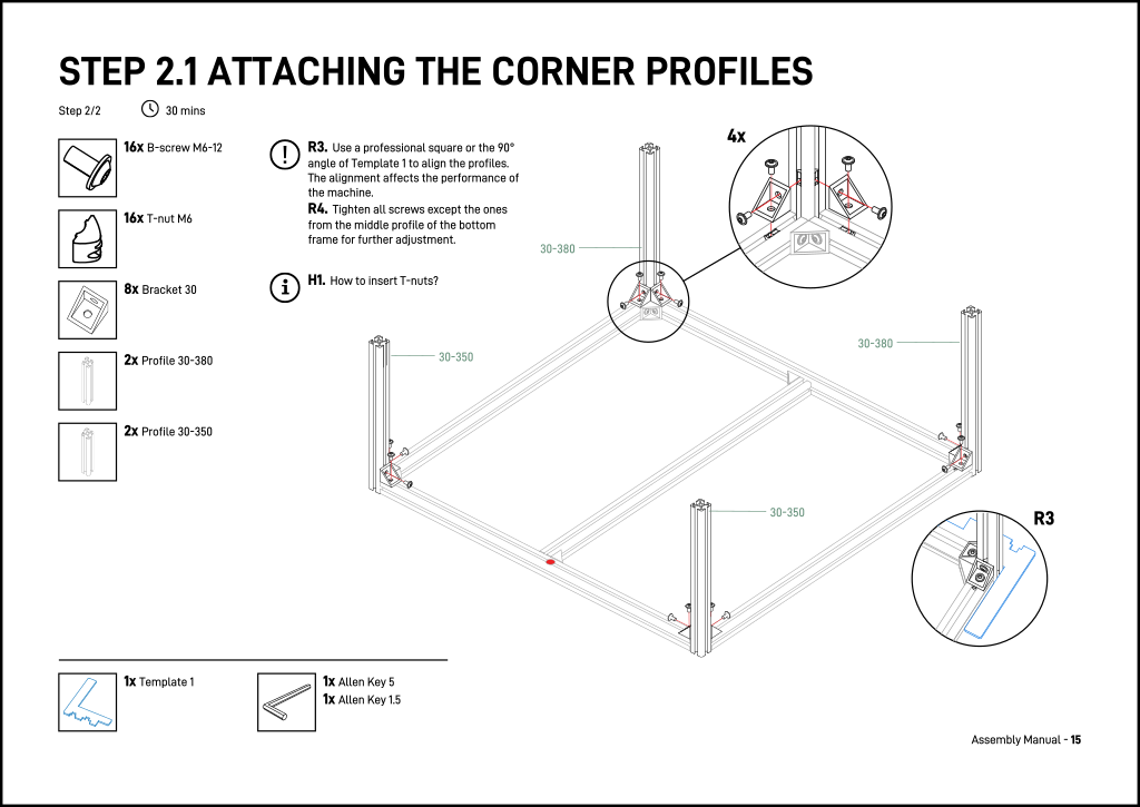
OSH Automated Documentation is software that allows you to generate high-quality visual assembly instructions for physical products designed in CAD software, for example high-quality assembly instructions such as for the Fabulaser Mini laser cutter:
Overview
This software is part of a peer-reviewed article and as such still research software and not production ready. By popular demand we are actively searching for funding to continue this work and make it production ready.
How does it work
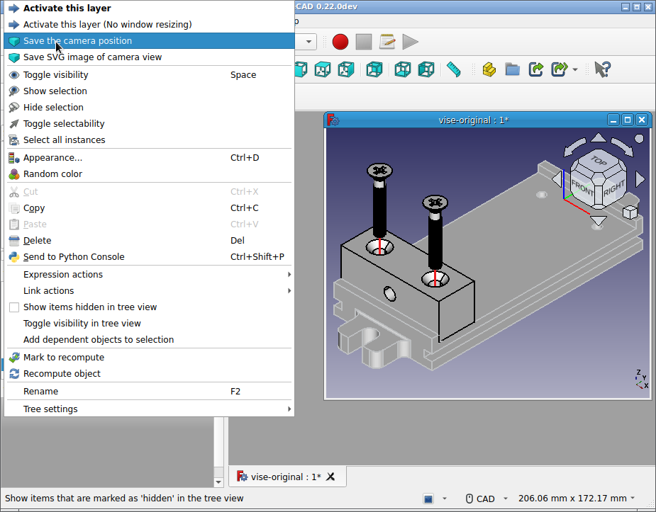
The software consists of a workbench for FreeCAD and a compiler that generates a PDF based on a textual description of the manual. The workbench is used to make annotations to the CAD model, for example a STEP file. An example of such an annotation is in the figure below where the camera position is saved to for generating a high-quality image for in the manual:
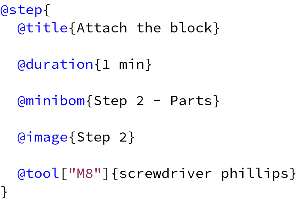
The textual description provides ways to define an assembly step in the process. It allows you to refer to the annotation in the CAD file; in the example below it refers to a layer called "Step 2 - Parts" that contains the parts for a step, and to a layer state called "Step 2" that is the basis for the main image:
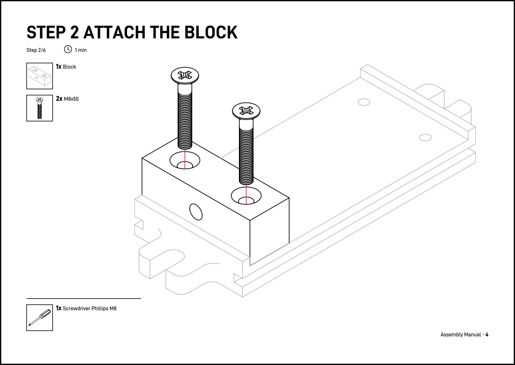
With this information, the compiler creates a page for the assembly step with a visual BOM for the parts and the main image for the page:
On changes in the design, the images and BOM can be automatically updated to reflect these changes in the assembly instructions.
Motivation
In engineering in general, it is difficult to keep documentation up-to-date with evolving designs. This is especially true for Open Source Hardware where documentation is a crucial aspect: without documentation there is no open source hardware. As soon as a project gains traction, and multiple persons contribute to the designs, the documentation is even more challenging to keep up-to-date.
An often seen problem is that projects have multiple sources of truth: there is the CAD design as one source of truth and there is documentation such as assembly instructions, another source of truth. These sources of truth can become disconnected from each other.
With our software, we aim to make the "source footprint" of the hardware as small as possible, relying as much as possible on the CAD designs as the source of truth, add annotations to the design and a minimal textual specification as source of truth that refers to the CAD design. From this minimized source footprint we generate the documentation.
Our project first focuses on assembly instructions, but in the future we would like to capture more documentation in the same way, such as design rationales, documentation to manufacture parts, electronics, maintenance instructions, and user manuals.
More information
The various software packages can be found in our osh-autodoc repository. For background we refer to our open access, peer-reviewed paper. The workbench has been released under the FreeCAD compatible LGPL license and the compiler under the AGPL license.
Installation
The software consists of two software packages that closely interact: the FreeCAD OSH Automated Documentation Workbench and the compiler to generate the assembly manual in PDF. The packages work closely together but they can in principle be used separately. Currently, the software is only supported on Linux. The software is in the pipeline to be released in official repositories allowing easy installation but until then, we provide installation scripts.
The workbench currently requires a very recent version of FreeCAD greater than the current stable version 0.21.2. The best option is to install a development version. The next major release of FreeCAD will support the features that are required for the workbench, so using a development version is temporary. The workbench is available in the addon manager of FreeCAD for easy installation.
The compiler and dependencies can be installed via Roswell. Currently it requires a separate script but as soon as the compiler is added to Quicklisp, installation will require only one command.
For the installation we assume a Linux machine with Bash as shell. Please adjust the commands accordingly for different shells.
Acquiring the installation scripts:
git clone https://codeberg.org/osh-autodoc/scripts-install-osh-autodoc.gitTemporarily add the installation scripts to the path:
export PATH="$PATH:$(realpath scripts-install-osh-autodoc)/bin"The workbench
The workbench requires a recent version of FreeCAD greater than the current stable version 0.21.2. We first focus on installing FreeCAD and then on the workbench itself.
Installing a recent version of FreeCAD
The best option is installing a development version of FreeCAD. On FreeCAD’s download page you find the option "Development versions". These versions are recent enough to support the workbench. Note that although the workbench is supported on all platforms, only Linux is supported for the compiler. Follow the installation instructions for either Conda, Snap, or Flatpak.
Install the workbench
The workbench is available in FreeCAD’s Addon Manager. To install it, launch FreeCAD and go to Tools → Addon Manager and search for "OSH Automated Documentation". Select the workbench and press "Install" to install it.
The PDF compiler
The compiler and dependencies can be installed via Roswell, which is prerequisite software. Please install it as explained in the documentation. Additionally, the compiler requires Inkscape for processing SVG images. Prerequisites for executing the script are:
The PDF compiler can then be installed with the following command:
install-pdf-compilerIt is convenient to have the command osh-autodoc-pdf available in the shell.
For Bash, we can execute the following to store the following in the PATH:
echo "export PATH=\"\$PATH:\$HOME/.roswell/bin\"" >> $HOME/.bashrcAdditionally, it is convenient to tell osh-autodoc-pdf where the resource
files are located. We can either use the flags -r or --res on the command
line, or we can set an environment variable. The latter is recommended and in
that case, please execute:
echo "export OSH_AUTODOC_PDF_RES_DIR=\"$HOME/.roswell/local-projects/osh-autodoc-pdf/res\"" >> $HOME/.bashrcSource the Bash resource file to make these settings available:
source $HOME/.bashrcRemoval of installation files
The following installation files can be removed after installation:
-
the directory
script-install-osh-autodocwherever it has been stored and -
the following tarballs:
-
cl-scribble-subset-parser-v*.tar.gz -
osh-autodoc-base-v*.tar.gz -
osh-autodoc-pdf-v*.tar.gz
-
If the need arises to remove the complete installation of the packages, the following file has been touched by this installation:
-
$HOME/.bashrc, remove the relevant lines.
The following directories are part of this installation:
-
$HOME/.roswell(unless used for other programs) and -
$HOME/.local/share/FreeCAD/Mod/osh-autodoc-workbench.
The latter directory is managed by the Addon Manager from where the workbench can be removed.
Manual
To create assembly instructions from a CAD file, there are several steps to follow. Below a list of the various steps for a basic manual:
-
Rename parts
-
Investigate the design for assembly step subdivision
-
Select parts for steps
-
Define positions for partly exploded views
-
Define a layer state for each step
-
Choose a camera position for each step
-
Initialize the Scribble template
-
Export SVG images for each step
-
Export BOMs for each step
-
Fill out the Scribble template with this information
-
Generate the PDF
We will follow these steps while creating a manual for the file
vise-original.FCStd
found in the osh-autodoc-data repository.
Rename parts
It is not strictly necessary to rename parts, but the labels for each part are used for 1) the BOM and 2) for detecting similar parts. If name changes in the design are not favored, then it is possible to rename the labels of the links later on. Examples of good names are:
-
M5 Nut
-
M3 Screw
-
M3 Screw 001
-
M3 Screw 002
-
M3 Screw 003
-
M5 Nut001
-
M5 Nut001
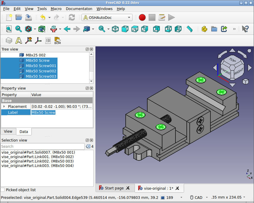
In FreeCAD it is possible to select multiple parts at once and rename them in one go by editing the Label field for all those parts:
The file with the vise has the names already as we would like. Since this
particular design has no nuts, we do not have to specify whether M8x50 is a
nut or screw, so M8x50 is enough information to understand which part is
needed.
Investigate the design
Something that is difficult to automate is how to break down the different parts in assembly steps and substeps. This does not necessarily follow the same approach as how the object was designed. Often this step simply involves inspecting the CAD design to get a rough idea on how you would want to approach assembly an object.
A good rule of thumb is that an assembly step or substep has a maximum of seven different parts as this is the maximum amount we can show on a page of the assembly manual.
For the vise, we want to divide the steps as such:
1. Align the base plate. This helps us to understand where different parts have to be attached.
2. Attach the block.
3. Attach the fixed jaw.
4.1 Align the sliding jaw.
4.2 Attach the sliding jaw.
5 Insert the screw.
As soon there is a clear idea on how to subdivide the object in assembly steps, we can move on to the next step, selecting parts for the assembly steps.
Select parts for steps
Now that we have determined the steps, we can select the various parts that are
required for the steps. To define the parts for a step, we create a layer for
each step using the regular FreeCAD layer button
![]() and name those
layers:
and name those
layers:
-
Step 1 - Parts
-
Step 2 - Parts
-
Step 3 - Parts
-
Step 4.1 - Parts
-
Step 4.2 - Parts
-
Step 5 - Parts
These layers will contain links to the parts that are required for these particular steps. These layers will provide the basis to generate a BOM.
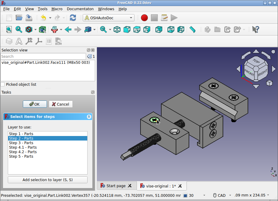
To perform this action, we make all the parts of the file visible and use the
Step select button ![]() to select parts.
A task will open that allows you to select a layer, and given this layer, we
can select the parts and press
to select parts.
A task will open that allows you to select a layer, and given this layer, we
can select the parts and press S, S to add them to the layer.
The part will disappear to make it possible to uncover hidden items that should be part of this step. If satisfied with the selection of parts for this assembly step, we can select the next layer "Step 2 - Parts" and select the parts for those:
After completion of this step, layers have been created that contain the parts for each step. Each part is represented by a link to the original part.
Define positions
In this step, we will create additional layers that will contain the "positions", a special construct of this workbench that provides a partly exploded view for screws and nuts.
We want to define additional layers for the positions and since Step 2, Step 3, Step 4.2 and Step 5 have parts that need to be positioned in a particular way, we will create layers for those, named:
-
Step 2 - Positions
-
Step 3 - Positions
-
Step 4.2 - Positions
-
Step 5 - Positions
To create the positions, we will first make sure that the original object is invisible and all the layers and their parts are visible.
We create positions with the position button
![]() . For each
selected object, it will create a position object. This position object can be
positioned somewhere in the document that conveys how to place or insert the
part.
. For each
selected object, it will create a position object. This position object can be
positioned somewhere in the document that conveys how to place or insert the
part.
For screws, it is possible to infer how they should be positioned. Therefore,
there is a special "Position Screws" button
![]() .
This button places screws with a red line showing the user how to insert the
screw.
.
This button places screws with a red line showing the user how to insert the
screw.
Let’s show how to use positions for Step 4.2. We select the two screws and use the "Position screws button":
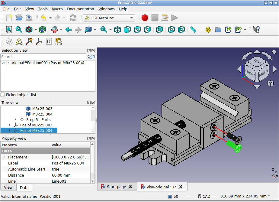
The created position objects contain a line object that shows a red line indicating how to insert the screws. The Position object has the properties Distance that controls the distance from where the screws should be placed and "Automatic Line Start" that controls whether the red line should be shown.
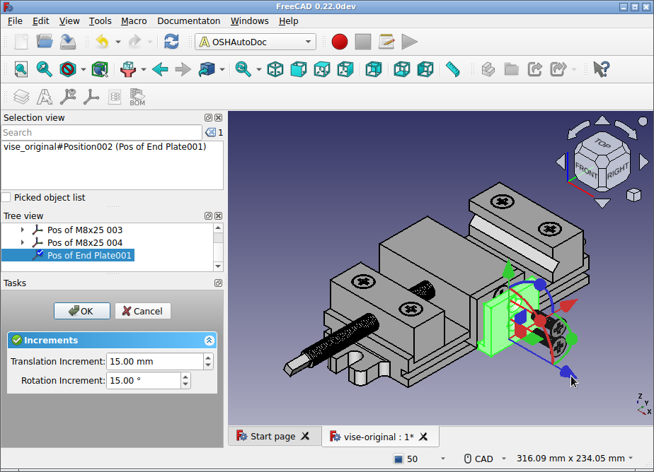
For the L-shaped object, we cannot infer how to place it. We therefore select
the L-shaped part in the 3D view and apply the normal position button
![]() .
.
This creates a new Position object on which we right click, to apply "Transform", moving the object to the location we want:
After we have done this, we move the positions to the "Step 4.2 - Positions" layer. Making this layer visible and invisble shows the difference between the positioned and the non-positioned parts.
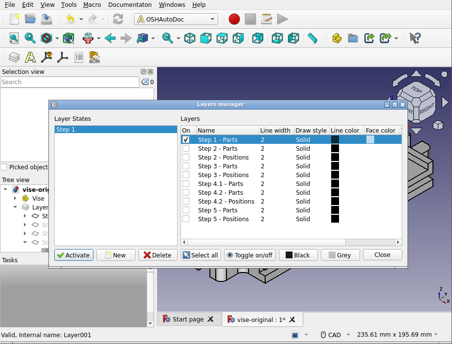
Define layer states
After defining the positions for each of the steps, we can move on to create a
layer state for each step. To do so, we open the Layer State Manager with the
Layer State Manager button ![]() .
.
For the vise, we will create 5 layer states, for each of the steps. First, we create a new layer state with "New" that we will call "Step 1" and on creation you can see each layer represented in the right pane. We will only select the first layer "Step 1 - Parts" and press "Activate". Note that the "Activate" button stores all the information for the layer state, so after a change to the layer states, the "Activate" button should always be used.
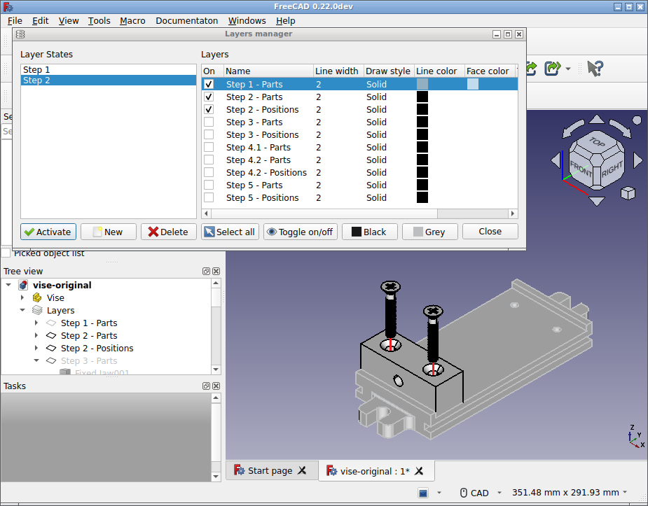
For the next assembly step we can select the previous layer state and create a new one based on that calling it "Step 2". For this one, we enable the layers "Step 2 - Parts" and "Step 2 - Positions" and we make sure that "Step 1 - Parts" is greyed out.
We can finish this for each step and close the layer state manager.
Choose a camera position for each step
For each of the layer states, we can define camera positions to create images for the assembly instructions. We can apply Windows → Tile in the menu and use the frame of the 3D viewer to define the boundaries of the SVG that we want to create.
To define the camera position for Step 1, we activate the layer state "Step 1" by right clicking and select "Activate this layer". We then modify the frame of the 3D view such that it about a square (no need to be precise). We then zoom, rotate, and pan in such a way that it is clear how to proceed in this assembly step. Below is a screenshot for Step 2 that shows how the vise is placed in the frame of the 3D viewer and the right click on the layer state to save the camera position:
We can do this for each layer state and afterwards each time a layer state is activated, the window will be restored as defined in this step.
Initialize the Scribble template
We are now almost ready to focus on the actual assembly instructions. Let us
first copy the Scribble template and compile it for a first time. Let’s assume
we want to have a directory doc-vise with the source of the assembly
instructions.
Let’s first copy the template:
cp -r $HOME/.roswell/local-projects/osh-autodoc-pdf/res/template doc-vise
cd doc-vise
Let’s compile the (empty) assembly instructions for a first time:
osh-autodoc-pdf index.scrblThis should give us a file assembly-instructions.pdf with empty instructions.
Coincidentally, the structure of the steps is already matching the structure of
the vise.
Export SVG images for each step
Now that we have a directory for the assembly instructions, we can export an
SVG image for the step by rightclicking on the layer state and choose "Save SVG
image of camera view". Let’s store the image in directory doc-vise/img:
The resulting image should exactly match the frame of the 3D viewer:

We can repeat this for each step.
Export BOMs for each step
Now that we have all the main images for each step, we can focus on creating
the Bill of Materials for each step. We select all the layers with parts, so
"Step 1 - Parts", "Step 2 - Parts", etc. We then use the Export BOM button
![]() and store the generated information in directory
and store the generated information in directory
doc-vise/img.
Fill out the Scribble template
Given this information we can fill out the Scribble template. We will focus on the steps themselves:
For each of the steps we fill out the following information: In step1.scrbl
files, we use @img{Step 1} and @mini-bom{Step 1 - Parts} referring to the
layer state and part layer respectively. We can also name this step by filling
in the title like so @title{Align the base plate}. The name has been taken
from what we determined earlier to be the steps.
Let’s take a look at an example for Step 2 in file step2.scrbl. For this
step, we also provide the suggestion to use a Phillips screwdriver. The
template already contains an SVG image for this tool.
The contents of the file should then look like this:
Generate the PDF
After we filled out the information in the Scribble files, we can generate the assembly instructions:
osh-autodoc-pdf index.scrblThis will give us the following page:
We can repeat these actions for all the other assembly step. It is also useful to create a layer state for the final assembled product and store the camera position to create an SVG image for the fully assembled model as well. This image can be used on the front-page of the assembly instructions.